Vous aimez la série Ricky la belle vie, Julio Iglésias ou l'émission Kohlanta ? Alors soyez les bienvenus sur Gamoover ! [/move]
Hi All,
Sorry, I forgot to add some useful information regarding the Triac in the motor controller.
Initially I thought the original G-loc Triac was faulty. When testing with my "universal" tester, it showed as a resistor :(
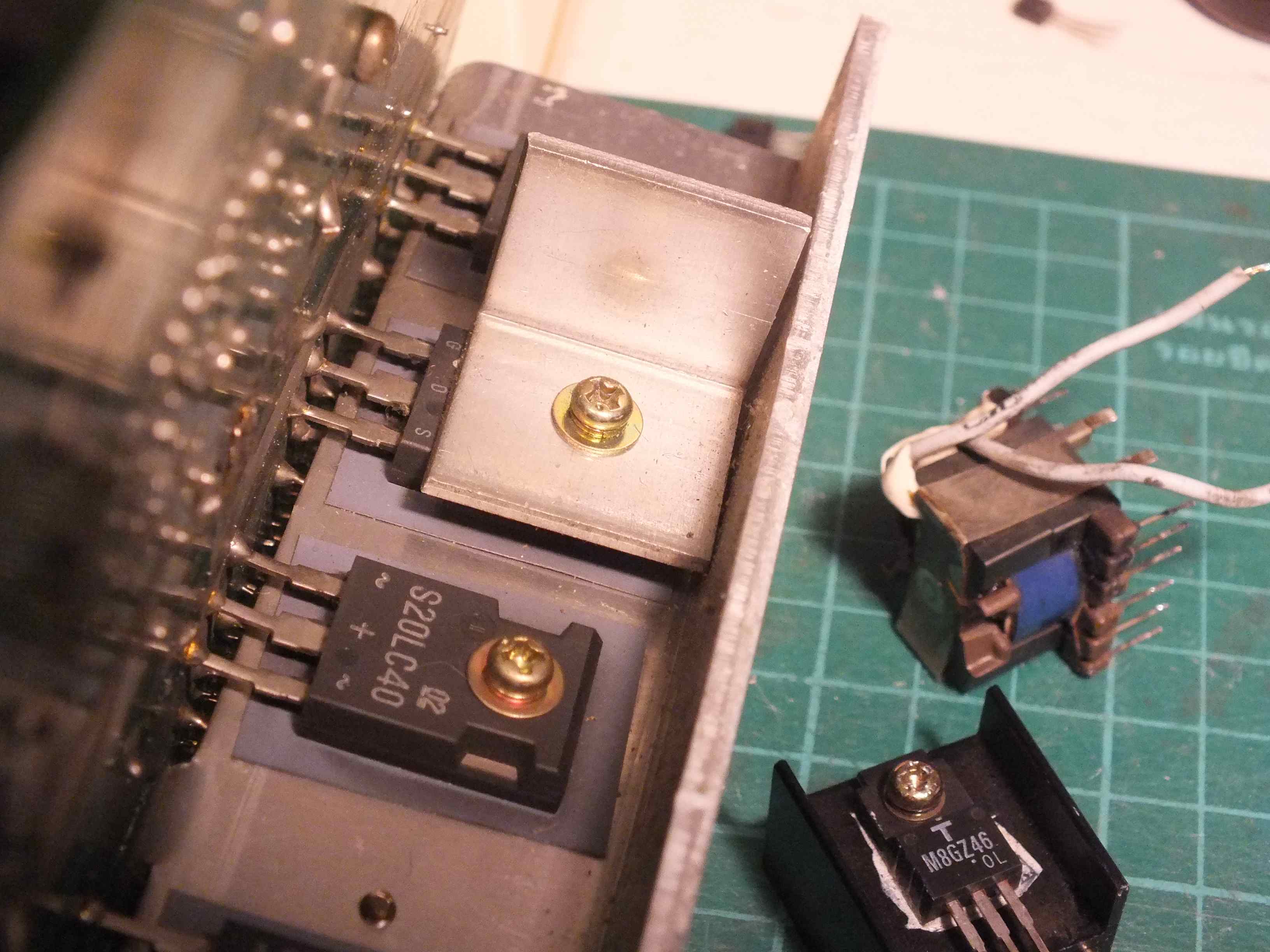
So I bought a replacement Triac which was a little higher rating: BTA10-600C
It has a metal tab, but it's still insulated like the original.
Before installing the new Triac, I tested, and found it to measure the same as the original:

I thought the new Triac was faulty from the shop
But then I thought the tester was faulty.
I found an old Triac which I had from another project, TIC226, and the tester detected a good Triac:

Now I begin to think the original Triac and the new BTA10-600C were faulty, but before I complain to the shop, I have to be sure what I'm talking about. Could it be that the tester cannot correctly test sensitive gate Triac's ? The old TIC226 was not a sensitive gate Triac, so that makes me think that there's a design limit with the tester
I need another way of testing a Triac. A Google search shows there are lot's of simple (low voltage) tests, but I wanted something which would test the Triac under a greater load, but still reasonably safe to operate.
I had a GE3020 (same as a MOC3020) opto-coupler which has a Triac output and can trigger a larger Triac, and the input is isolated, so it's reasonably safe.
Here's an extract from the MOC3020 datasheet:

I built the sensitive-gate version, with a jumper to short out the 2.4K resistor to test older Triac's which need greater trigger current. I used a 390ohm resistor for Rin, so I can use 5VDC to trigger the tester. I also connected a 3mm LED to the input as an indicator so I can confirm when 5V is connected to the input. I also have a small socket for the Triac under test. With this circuit I can test almost any Triac with mains voltage and a few amps of current if I like.
Here's what it looks like:

By the way, we have 240VAC mains in Australia, so the 220VAC on the circuit is good. Those in Japan or USA will need to adjust the 180ohm and 2.4K resistors - check the datasheet for the opto-coupler.
With my tester, all Triac's worked, including the original G-loc Triac
Even the old TIC226 tested perfect in the sensitive gate configuration of the circuit.
I put the original G-loc Triac back in the motor controller
In the end it was a very good learning experience. I found that some test equipment cannot test what might be expected, and so have to build my own test gear.
Cheers for now.
Sorry, I forgot to add some useful information regarding the Triac in the motor controller.
Initially I thought the original G-loc Triac was faulty. When testing with my "universal" tester, it showed as a resistor :(
So I bought a replacement Triac which was a little higher rating: BTA10-600C
It has a metal tab, but it's still insulated like the original.
Before installing the new Triac, I tested, and found it to measure the same as the original:

I thought the new Triac was faulty from the shop
But then I thought the tester was faulty.
I found an old Triac which I had from another project, TIC226, and the tester detected a good Triac:

Now I begin to think the original Triac and the new BTA10-600C were faulty, but before I complain to the shop, I have to be sure what I'm talking about. Could it be that the tester cannot correctly test sensitive gate Triac's ? The old TIC226 was not a sensitive gate Triac, so that makes me think that there's a design limit with the tester
I need another way of testing a Triac. A Google search shows there are lot's of simple (low voltage) tests, but I wanted something which would test the Triac under a greater load, but still reasonably safe to operate.
I had a GE3020 (same as a MOC3020) opto-coupler which has a Triac output and can trigger a larger Triac, and the input is isolated, so it's reasonably safe.
Here's an extract from the MOC3020 datasheet:

I built the sensitive-gate version, with a jumper to short out the 2.4K resistor to test older Triac's which need greater trigger current. I used a 390ohm resistor for Rin, so I can use 5VDC to trigger the tester. I also connected a 3mm LED to the input as an indicator so I can confirm when 5V is connected to the input. I also have a small socket for the Triac under test. With this circuit I can test almost any Triac with mains voltage and a few amps of current if I like.
Here's what it looks like:
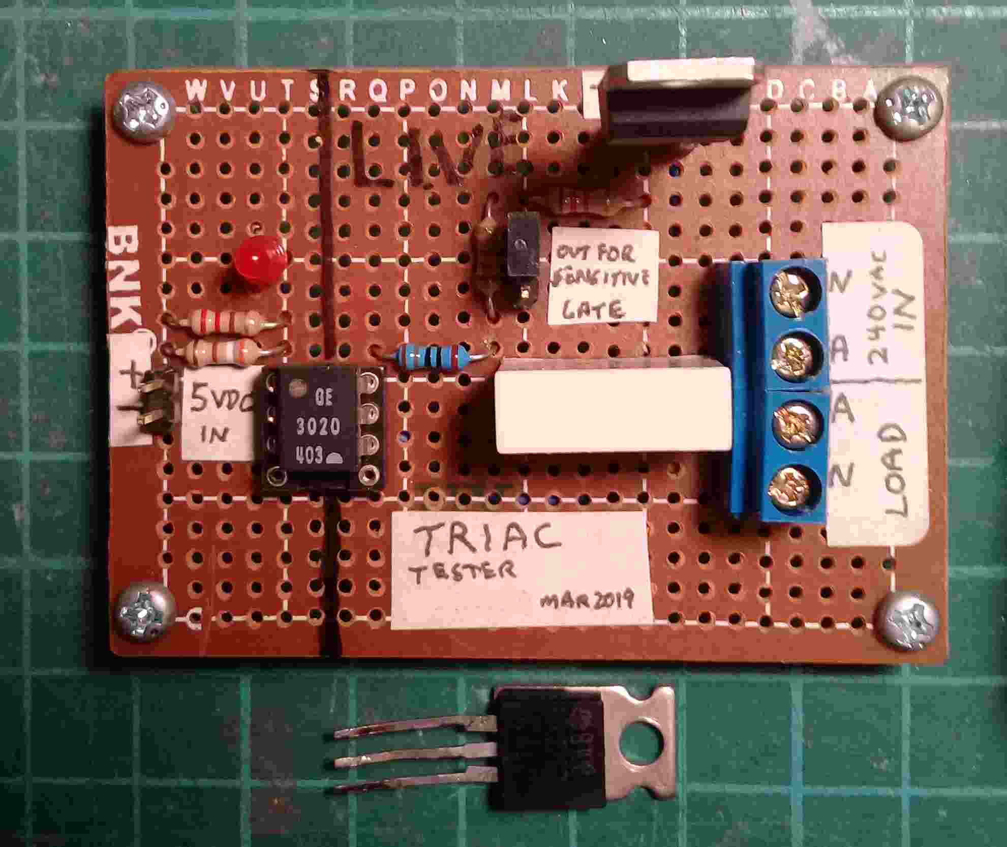
By the way, we have 240VAC mains in Australia, so the 220VAC on the circuit is good. Those in Japan or USA will need to adjust the 180ohm and 2.4K resistors - check the datasheet for the opto-coupler.
With my tester, all Triac's worked, including the original G-loc Triac
Even the old TIC226 tested perfect in the sensitive gate configuration of the circuit.
I put the original G-loc Triac back in the motor controller
In the end it was a very good learning experience. I found that some test equipment cannot test what might be expected, and so have to build my own test gear.
Cheers for now.
 It works like new.
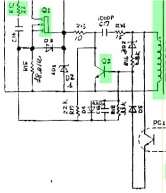
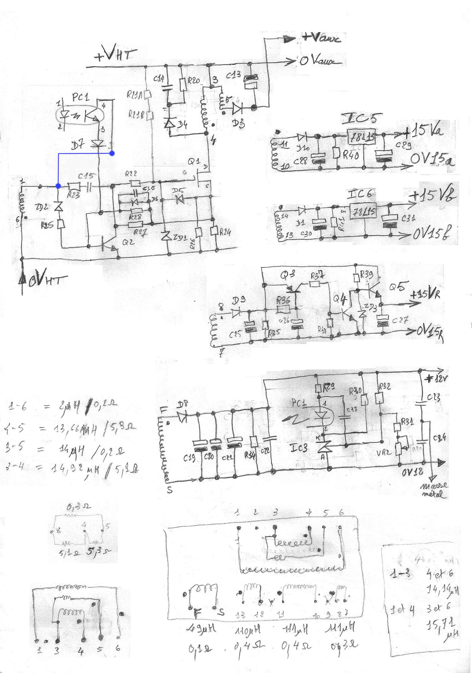
 This is what I want from the other 15V supply windings after rectification, so the 78L15 regulators (IC5 and IC6) can function correctly.