Gamoover

Vous aimez GAMOOVER ? Vous avez trouvé la perle rare grâce à notre forum ?
Alors pourquoi pas nous soutenir en effectuant un petit don Paypal sur : contribution@gamoover.net
C'est peut être un détail pour vous, mais nous, ça nous aiderait beaucoup !

Menu

Voir les contributions

Cette section vous permet de consulter les contributions (messages, sujets et fichiers joints) d'un utilisateur. Vous ne pourrez voir que les contributions des zones auxquelles vous avez accès.

Voir les contributions Menu

Messages - berty

#1
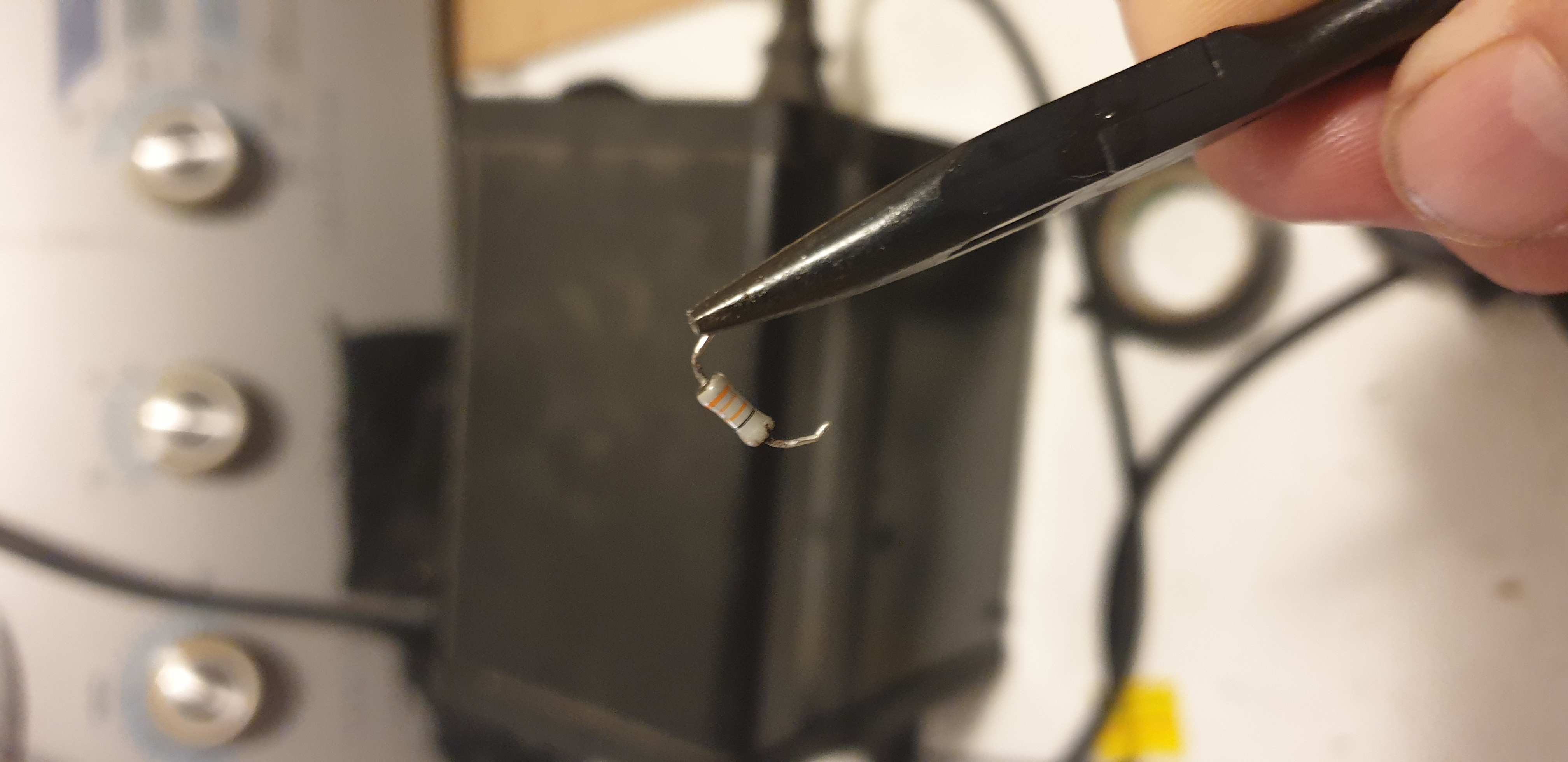
Pefect! R2 had failed.

I could only purchase 1.5 Ohm 5W resistors but they seem to be okay. Thanks again Per!

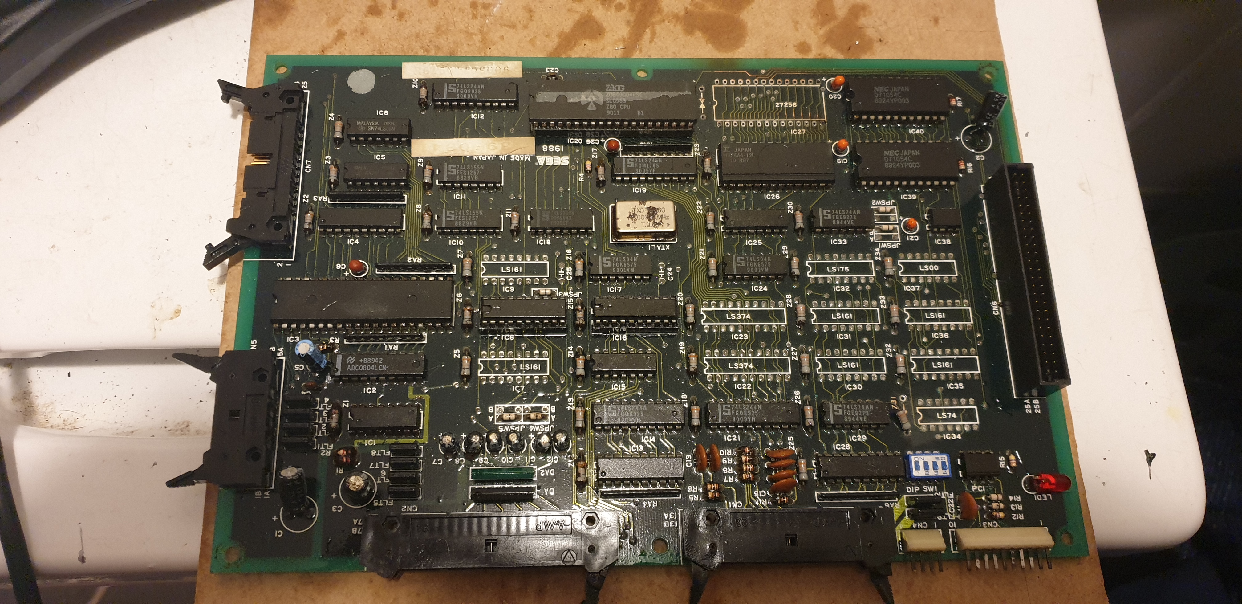
Now I need to find a working digital motor control board...
#2
Hi All.

Recently I repaired two Sega G-Loc motor power supply boards. The DC voltages on both boards were all tested and found to be working correctly as per the instructions here:
https://www.gamoover.net/Forums/index.php?topic=28660.0

After completing the repair, I plugged these boards back in to the machine, noting the Digital Motor Control Board was untested. The two motor power supplies were plugged into the digital motor control board BUT the digital motor control board was not plugged into the PCB.

Even though the digital motor control board, was not plugged into the PCB both of the motors moved on two separate occasions, causing the AC safety switch in the G-Loc machine to turn off.

After removing one of the power supply boards, I have found that the AC input into the L2 transformer drops from 340V AC down to about 260V AC when switched on. I suspect that one of the K1250's has blown, but I am seeking advice on trouble shooting before proceeding any further.

Here is a video of the issue.


#3
Citation de: berty le Vendredi 12 Février 2021, 12:59:22 PM
I need some help from @gc339 or others with experience.

I've recently rebuilt my SEGA 400-5117Y driver board using gc339's instructions here but I am still having trouble. I am not getting 5v DC at IC8 and I am not getting 12v DC at the fan point. Here is what I have found;

1. I am getting 305V DC the L2 Transformer and R24. (I am using the 100V AC input voltage from an isolation transformer).
2. When I remove D3, D4, D10 and D11 I can get 2.0V DC at the fan point
3. When I put D3, D4, D10 and D11 back in the board, I get 0V DC at the fan point.

ZD01 and ZD02 have tested fine. Here is a link to all of the parts that I have replaced.

https://docs.google.com/spreadsheets/d/1nvmMJfTJugMmD8D6rF05rTHo-9x-n6FYH5TrlbLBnp0/edit?usp=sharing

I fixed the issue. I had the wrong resistor at R24 - It should be 2.2 Ohm, not 220 Ohm.
#4
I need some help from @gc339 or others with experience.

I've recently rebuilt my SEGA 400-5117Y driver board using gc339's instructions here but I am still having trouble. I am not getting 5v DC at IC8 and I am not getting 12v DC at the fan point. Here is what I have found;

1. I am getting 305V DC the L2 Transformer and R24. (I am using the 100V AC input voltage from an isolation transformer).
2. When I remove D3, D4, D10 and D11 I can get 2.0V DC at the fan point
3. When I put D3, D4, D10 and D11 back in the board, I get 0V DC at the fan point.

ZD01 and ZD02 have tested fine. Here is a link to all of the parts that I have replaced.

https://docs.google.com/spreadsheets/d/1nvmMJfTJugMmD8D6rF05rTHo-9x-n6FYH5TrlbLBnp0/edit?usp=sharing
#5
Hi all - I'm having issues finding an exact replacement for the 33nf axial ceramic capacitor. I was able to source some film capacitors but they are too large.

I am wondering if I can use something like what is shown below;
https://www.jaycar.com.au/33nf-50vdc-ceramic-capacitors-pack-of-2/p/RC5354

#6
Does anyone on the forum own a Taito WGP DX / Deluxe Cabinet like the one pictured below?


I need to know if this version of the game uses the Taito Motor Control PCB which is the PCB on the right of the image below.


I've tried to find a digital copy of the manual to confirm but haven't had any luck.

Thanks in advance!  ^-^
#7
I've ran the component through two different component testers. Both testers read the component as a 33nf Capacitor! Does this sound right to people?


#8
Here is a picture of the PCB at location Z24.


@gc339 - thank you for the suggestion. I just bought one of those Chinese multifunction testers.
#9
Hi All,

Apologies for not being able to write messages in French. I was attracted to the forum because of the wealth of technical expertise here. I am an Australian collector of mainly 90s dedicated arcade machines. I enjoy fixing and restoring machines. My current project is a G-Loc Deluxe with significant corrosion issues.

I've started working on the 839-0213 PCB. I need to replace all of these components which are labelled as "Z##" but I cannot figure out what they are.


I think they are either a Zener or TVS diode, but I am not sure. The end with the orange bands is connected to +5VDC and the end with the black band is connected to ground.


Can anyone help me identify what these are so I can replace the corroded ones on my board?

Cheers